Body Worn Camera
Model: P1
FCC ID: 2BVFCP6-BC-V1
User Manual
Patrol 6, LLC
2843 E. Robin Lane
Phoenix, AZ 85050 USA
2843 E. Robin Lane
Phoenix, AZ 85050 USA
User Manual
The Patrol 6 P1 is a professional body worn camera designed for law enforcement, security, and public safety personnel. It provides continuous HD video recording, real-time evidence upload over LTE cellular networks, and cloud-managed operation through the Patrol 6 platform.
| Product Identification | |
|---|---|
| Product Name | Body Worn Camera |
| Model Number | P1 |
| Brand Name | Patrol 6 |
| FCC ID | 2BVFCP6-BC-V1 |
| Manufacturer | Patrol 6, LLC |
| Address | 2843 E. Robin Lane, Phoenix, AZ 85050 USA |
Inspect the package upon receipt. Contact Patrol 6 support if any items are missing or damaged.
| Item | Quantity |
|---|---|
| P1 Body Worn Camera | 1 |
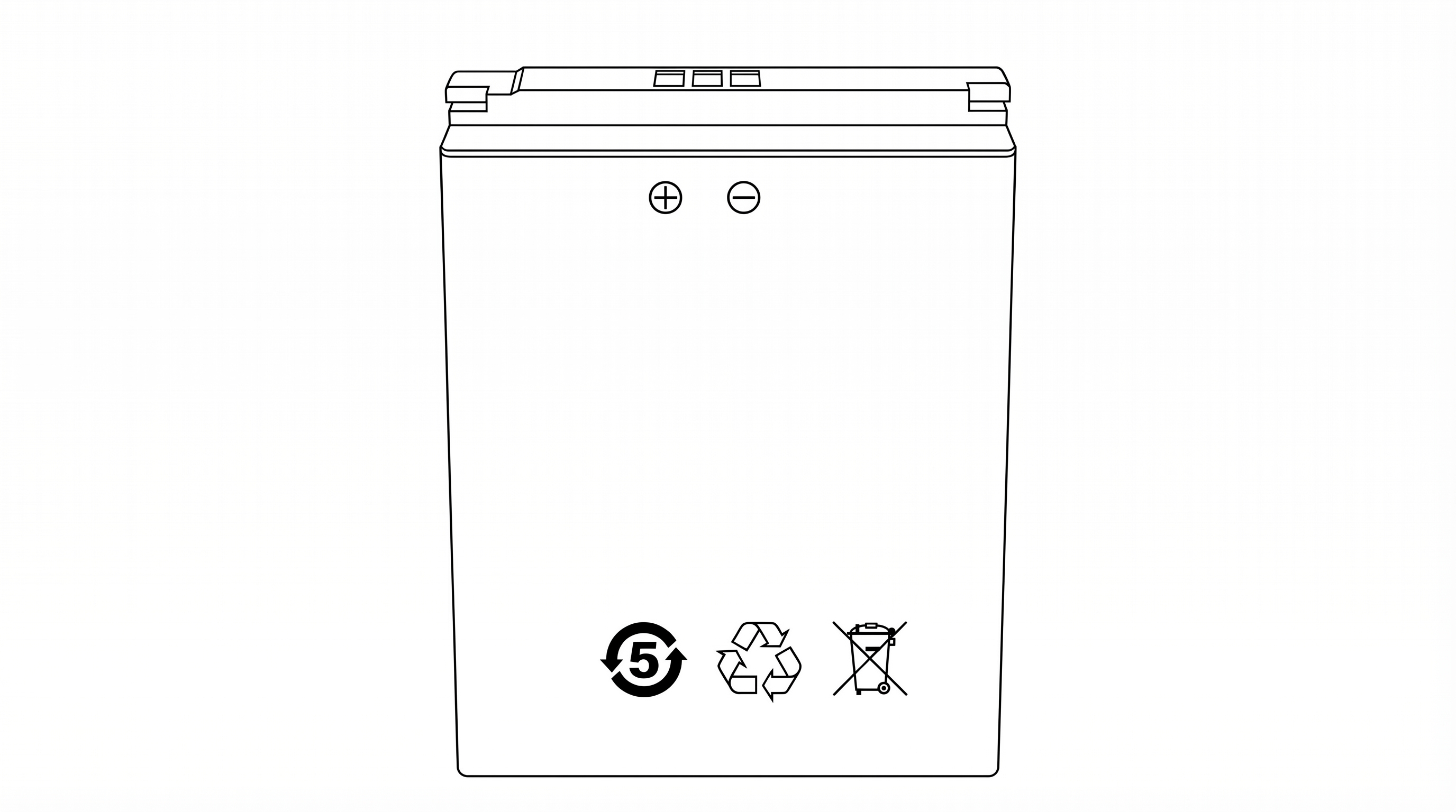
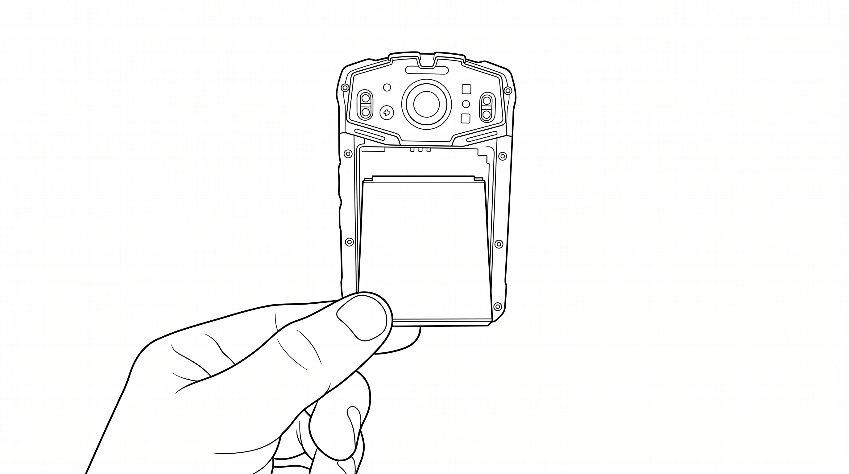
| Rechargeable Lithium-Ion Battery (3200 mAh) | 2 |
| Charging Cradle (camera + spare battery) | 1 |
| USB Wall Charger (5V/2A) | 1 |
| USB-A to USB-C Charging Cable | 1 |
| Rotating Alligator Clip (chest mount) | 1 |
| Vest Clip | 1 |
| Quick Start Guide and User Manual Card (QR code and URL to full online manual) | 1 |
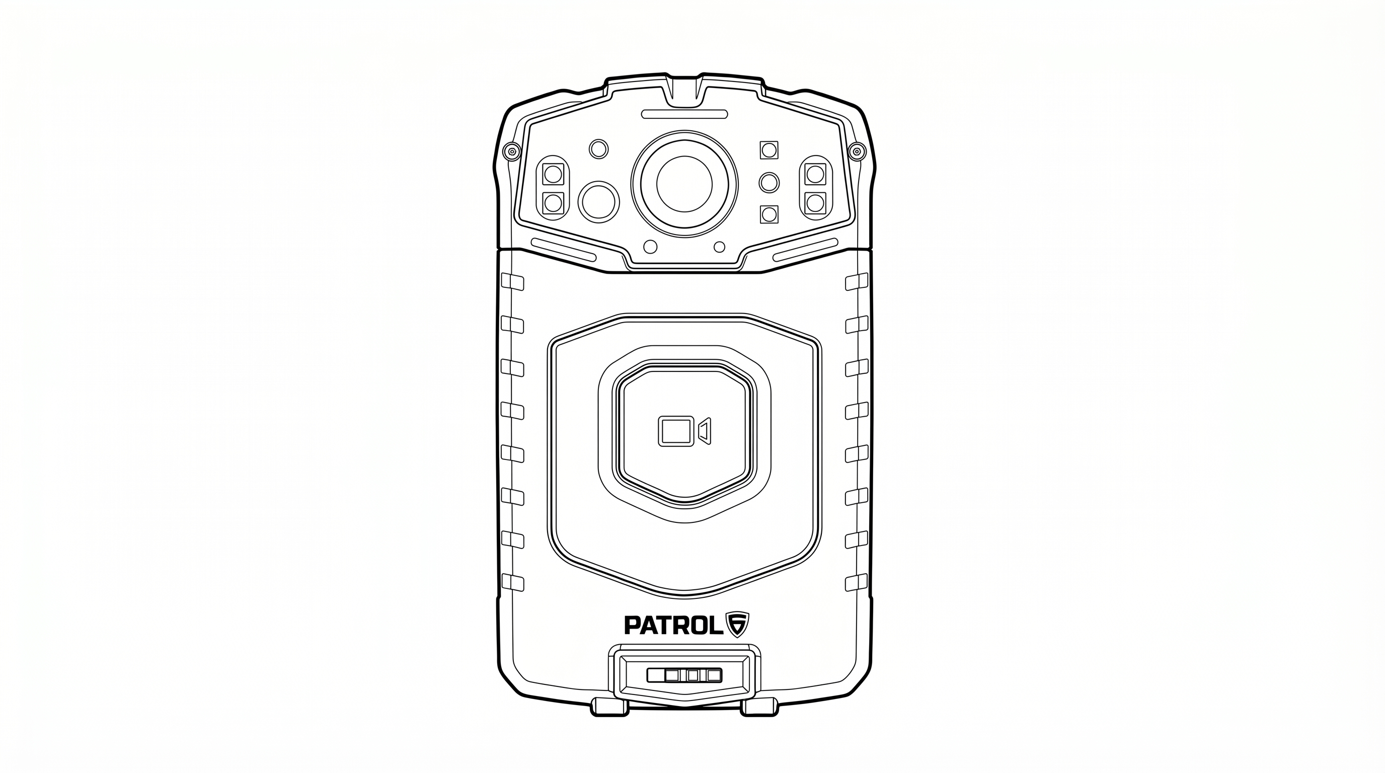
| Component | Description |
|---|---|
| Camera Lens | HD 120° wide-angle camera lens (top center) |
| IR LEDs | Infrared illuminators for night vision (flanking the lens) |
| Flash / White LED | Not used in current application |
| LED Indicators | Status LEDs indicating recording, charging, and device state |
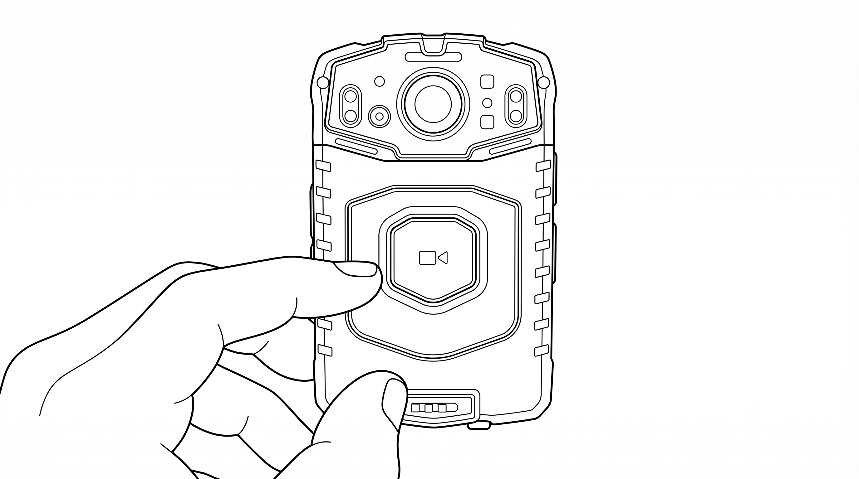
| Main Button | Center button with video camera icon. Short press: LiveAI trigger. Long press: Start/Stop event recording |
| Patrol 6 Logo | Brand identification |
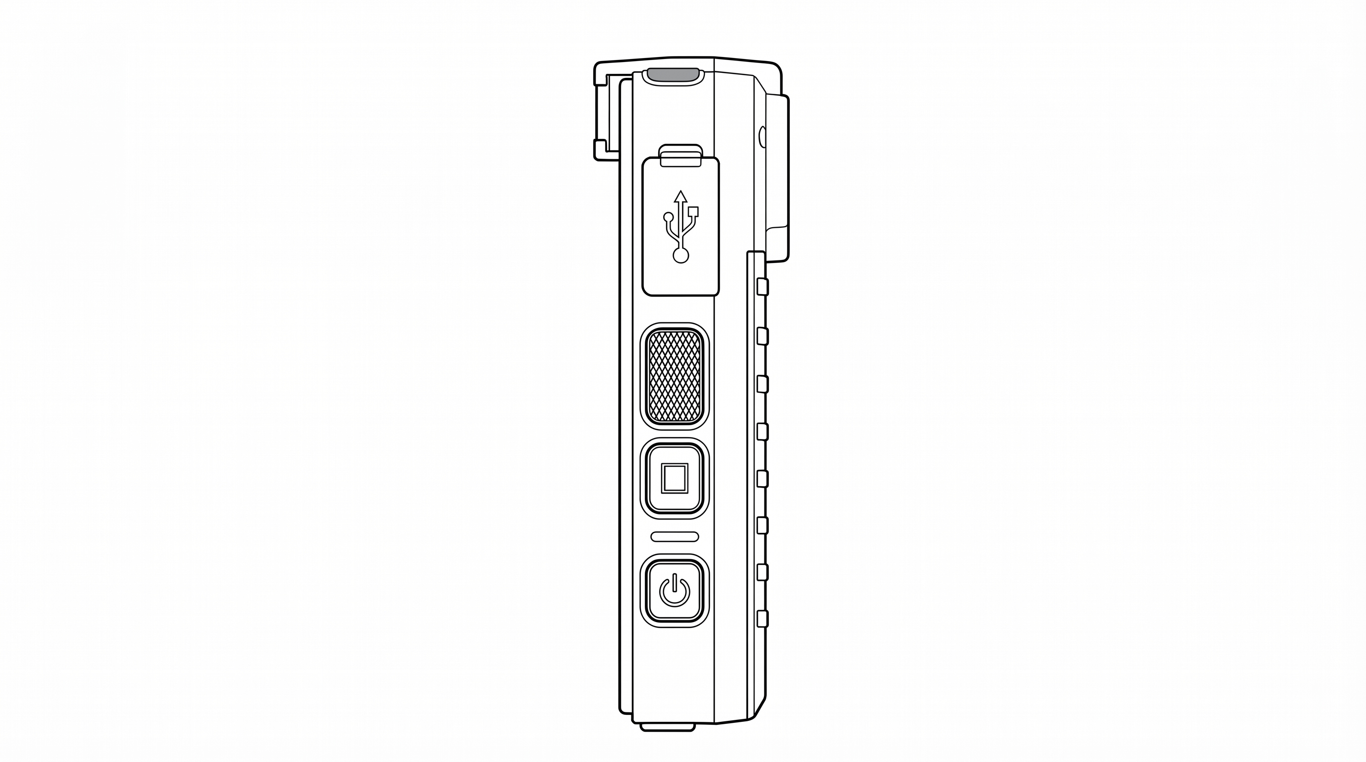
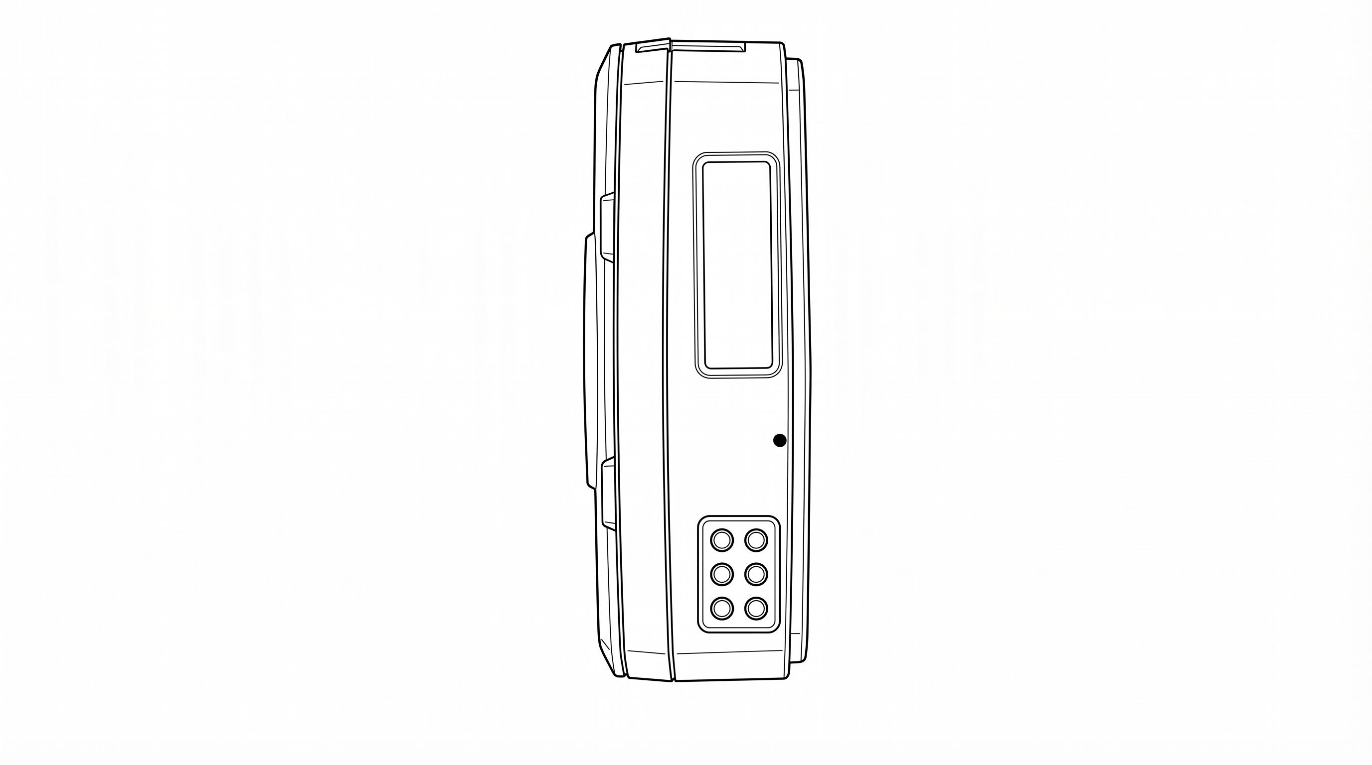
| Component | Description |
|---|---|
| USB-C Port | Behind protective flap (USB symbol on cover). For charging or data connection |
| Pause / Resume Button | Rectangular button. Short press: Pause recording. Long press: Resume recording |
| Snapshot Button | Short press: Capture a still photo. Long press: Toggle stealth mode on/off |
| Power Button | Bottom button with power icon. Short press: Screen sleep/wake. Long press: Power off / Reboot |
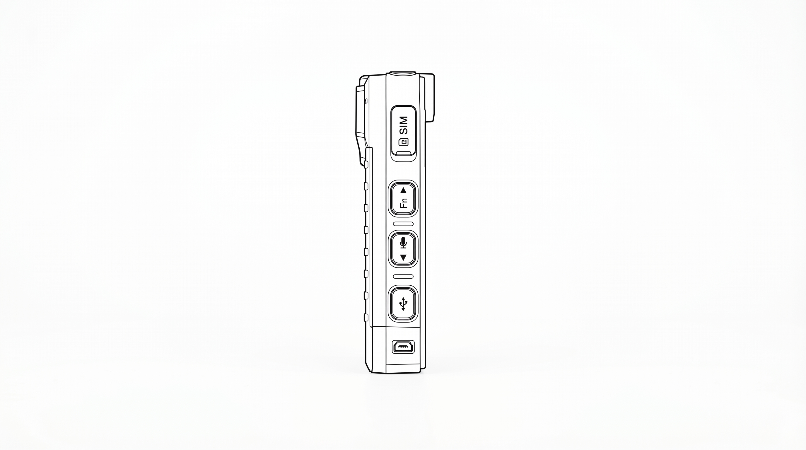
| Component | Description |
|---|---|
| SIM Card Slot | Behind protective cover (labeled "SIM"). For LTE nano-SIM card |
| Fn / Up Button | Volume up |
| Mic / Down Button | Volume down |
| Night Vision Button | Below Mic/Down. Toggle infrared night vision on/off |
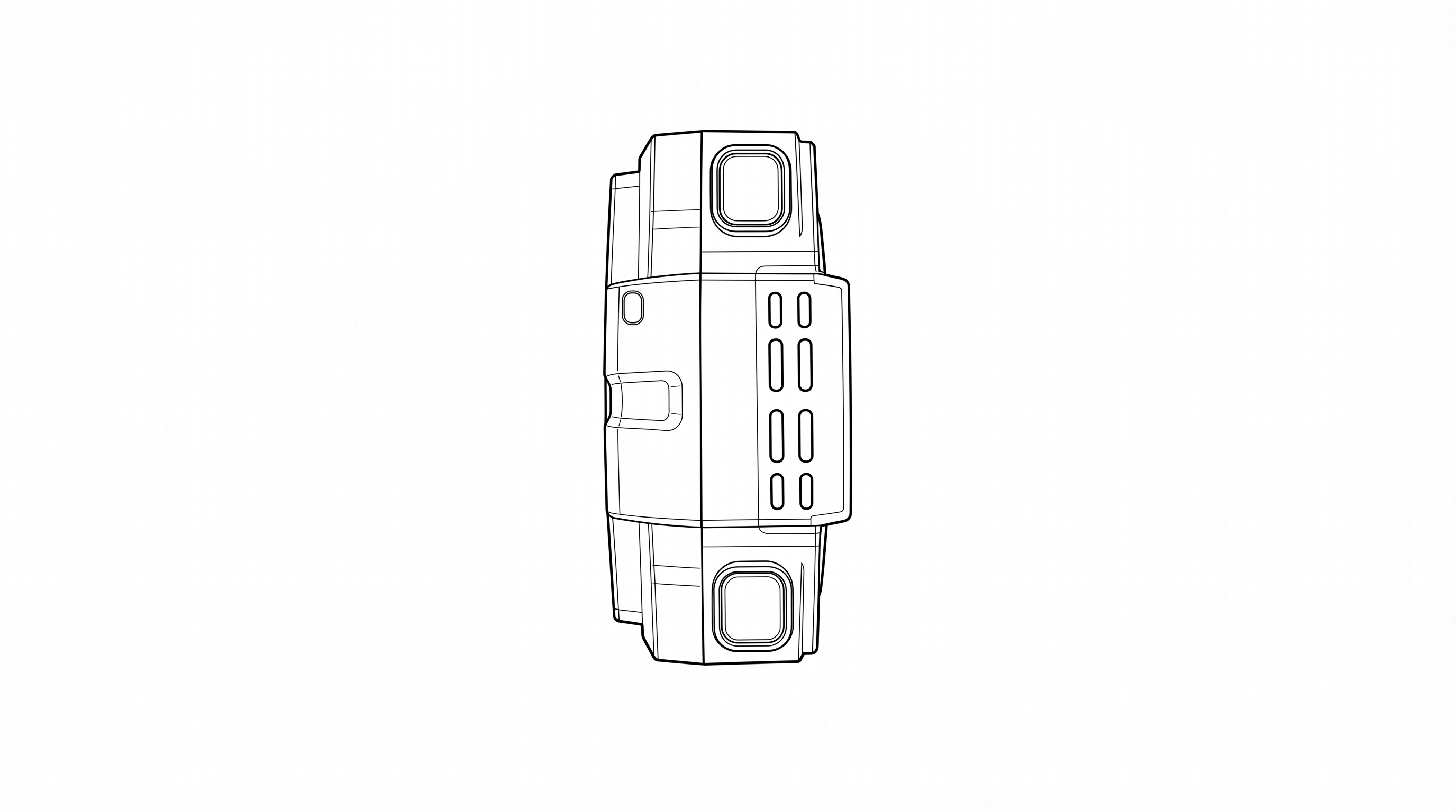
| Component | Description |
|---|---|
| Speaker | Speaker grille for audio playback and system sounds |
| Top-Right Button (Event) | Same as front Main Button. Short press: LiveAI trigger. Long press: Start/Stop event recording |
| Top-Left Button (SOS / AI) | Short press: Toggle AI on/off/low. Long press: Activate/Deactivate Panic/SOS mode |
The bottom features a 6-pin pogo connector for use with the charging cradle.
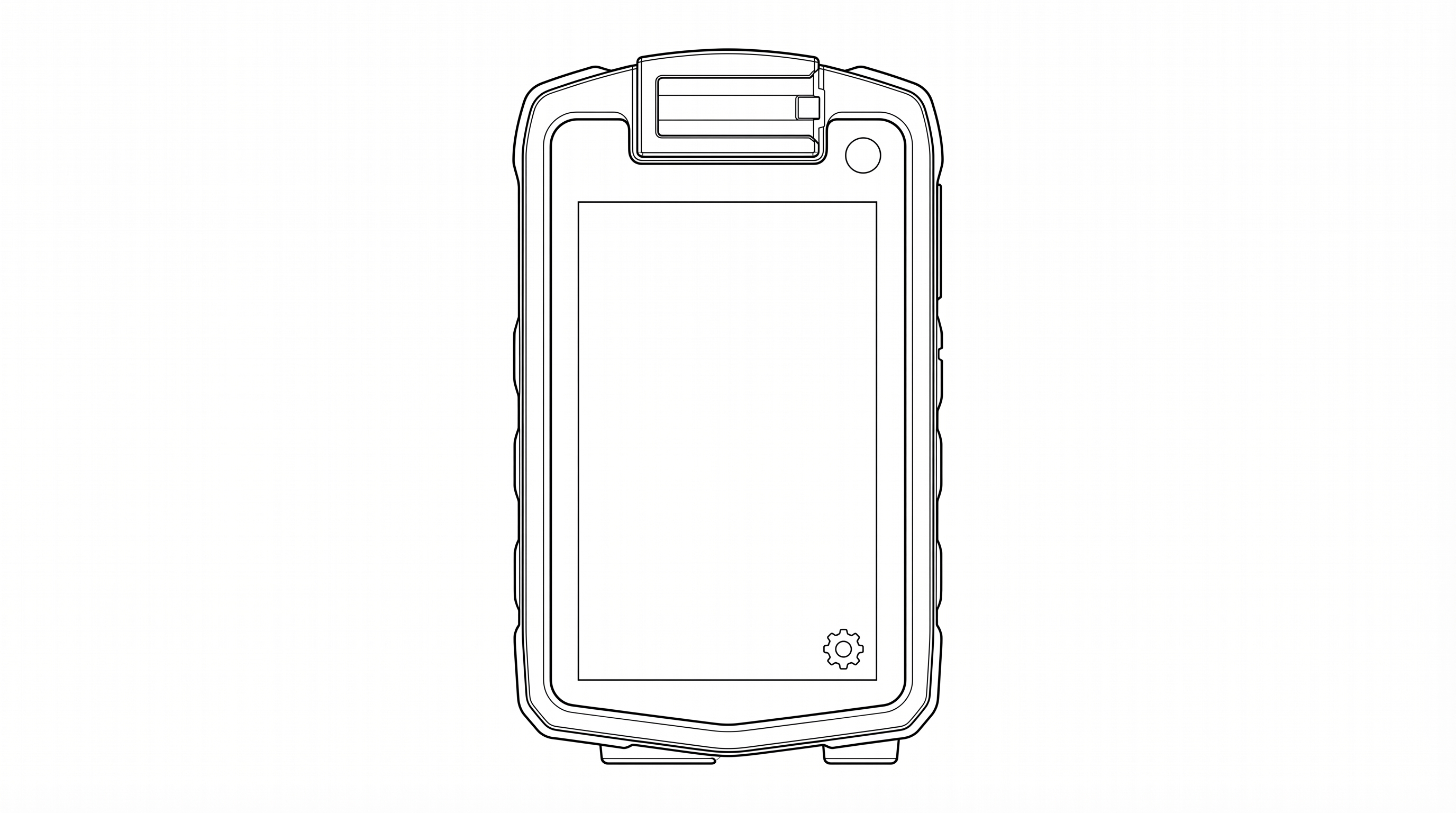
The rear of the device features a 3.1" IPS capacitive touchscreen display (480 x 800 pixels) used for system status, login, and settings. The rotating clip mount attaches at the top of the rear panel. A settings icon is visible at the bottom-right of the screen. Settings can be accessed before login if necessary.
The P1 can be charged two ways:
Method 1 — Charging Cradle (Recommended)
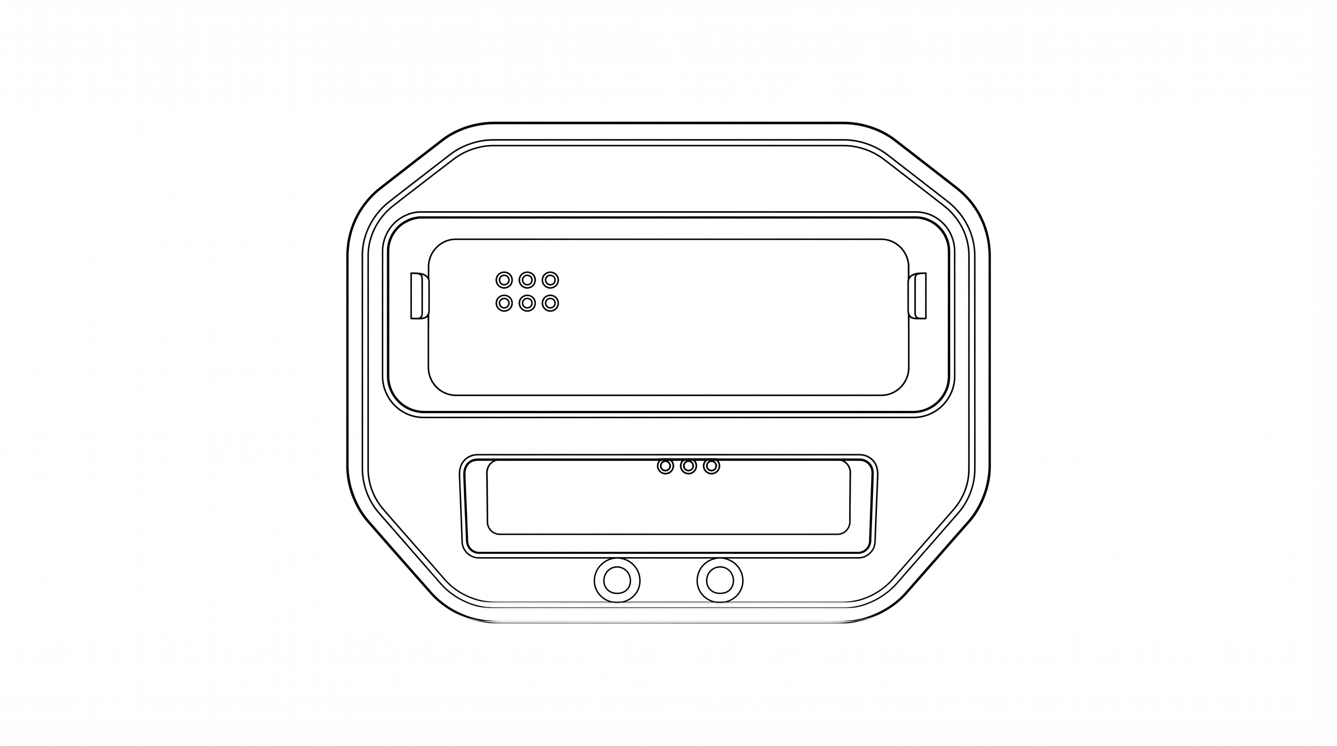
| Location | Red LED | Blue LED |
|---|---|---|
| Camera LEDs (on device) | Camera battery charging | Camera battery fully charged |
| Cradle LEDs (on cradle) | Spare battery charging | Spare battery fully charged |
Method 2 — Direct USB-C Cable
| Action | How |
|---|---|
| Power On | Long press the Power button (right side, bottom) for 3 seconds |
| Power Off | Long press the Power button for 3 seconds, then confirm on screen |
| Screen Sleep / Wake | Short press the Power button |
| Reboot | Long press the Power button and select Reboot from the on-screen menu |
The mount system supports:
Patrol recording is managed automatically by the Patrol 6 software. When a user logs in with their PIN and confirms their site assignment, recording begins automatically. Recording continues until the patrol is ended through the on-screen interface.
Event recording captures high-priority incidents with elevated upload priority.
During an event, both the red and blue LEDs will be illuminated. Event footage is uploaded with critical priority.
During a pause, the LED indicators will show green/yellow. Audio and video recording are suspended while paused.
Short press the Snapshot button (right side, below the Pause button) to capture a still photograph. Photos are saved alongside the video evidence for the current patrol session.
Long press the Snapshot button to toggle stealth mode on or off. In stealth mode, all LEDs and screen backlight are turned off for covert operation while recording continues.
The P1 features infrared night vision for low-light and no-light environments.
When activated, the IR LEDs illuminate the scene with infrared light invisible to the human eye, and the camera switches to IR capture mode.
The LiveAI assistant provides real-time situational awareness through voice interaction.
In an emergency, activate the Panic/SOS function to immediately alert your dispatch center.
This sends an immediate alert with your GPS location to the Patrol 6 management platform.
The AI assistant can be set to different modes to control its level of engagement.
| LED Color | Meaning |
|---|---|
| Red (solid) | Recording patrol video |
| Red + Blue (solid) | Recording an event (incident in progress) |
| Green / Yellow | Recording paused |
| Blue (solid) | Device is on but user is logged out |
| LED Color | Meaning |
|---|---|
| Red (solid) | Battery charging in progress |
| Blue (solid) | Battery fully charged |
| Button | Location | Short Press | Long Press |
|---|---|---|---|
| Main Button | Front center | LiveAI trigger | Start / Stop event recording |
| Top-Right Button | Right side, top | LiveAI trigger (same as Main) | Start / Stop event recording (same as Main) |
| Top-Left SOS Button | Left side, top (red button) | Toggle AI on / off / low | Activate / Deactivate Panic / SOS |
| Fn / Up | Left side | Volume up | — |
| Mic / Down | Left side | Volume down | — |
| Night Vision | Left side, lower | Toggle IR night vision on/off | — |
| Pause / Resume | Right side (rectangular) | Pause recording | Resume recording |
| Snapshot | Right side | Capture still photo | Toggle stealth mode on / off |
| Power | Right side, bottom | Screen sleep / wake | Power off / Reboot |
The included charging cradle provides two charging functions:
Setup:
| General | |
|---|---|
| Model | P1 |
| Dimensions | 103 mm x 63 mm x 22 mm (without clip) |
| Weight (with battery) | 208 g |
| Weight (without battery) | 180 g |
| Display | 3.1" IPS Screen with Capacitive Touch (480 x 800 pixels) |
| Ingress Protection | IP67 (dust-tight, submersible to 1 m for 30 min) |
| Operating Temperature | -20°C to 55°C (-4°F to 131°F) |
| Camera and Recording | |
|---|---|
| Video Resolution | HD 1280 x 720 @ 25 fps (software-configured) |
| Video Codec | H.264 |
| Hardware Capability | Up to 2K resolution |
| Audio | AAC-LC, 44.1 kHz, mono |
| Night Vision | Infrared LEDs, manual on/off |
| Photo Capture | JPEG still photos |
| Field of View | 120° wide angle |
| Storage | |
|---|---|
| Internal Storage | 32 GB |
| SD Card Storage | 256 GB (pre-installed, non-removable) |
| Battery | |
|---|---|
| Type | Rechargeable lithium-ion |
| Capacity | 3200 mAh |
| Voltage | 3.8V DC |
| Charging Input | 5V / 2A via USB-C or pogo-pin cradle |
| Included Batteries | 2 (one in camera, one spare) |
| Wireless Communications | |
|---|---|
| LTE Cellular | Bands 2, 4, 5, 12, 17, 30, 66, 71 |
| Wi-Fi | 802.11 a/b/g/n/ac (2.4 GHz and 5 GHz) |
| Bluetooth | Bluetooth EDR + Bluetooth Low Energy (BLE) |
| NFC | Near Field Communication |
| GPS | Built-in GPS for location tracking |
| Antenna | Internal (integral, non-removable) |
| Power Adapter (Included) | |
|---|---|
| Manufacturer | Dongguan Kaisheng Electronic Technology Co., Ltd. |
| Model | M4-050200A1-ETL |
| Input | 100–240V AC, 50/60 Hz, 0.3A |
| Output | 5V DC, 2A |
| Cable | USB-A to USB-C, 1.0 m |
For U-NII devices (5G WiFi):
The device for operation in the band 5150–5250 MHz is only for indoor use to reduce the potential for harmful interference to co-channel mobile satellite systems.
This device complies with Part 15 of the FCC Rules. Operation is subject to the following two conditions:
This equipment has been tested and found to comply with the limits for a Class B digital device, pursuant to Part 15 of the FCC Rules. These limits are designed to provide reasonable protection against harmful interference in a residential installation. This equipment generates, uses, and can radiate radio frequency energy and, if not installed and used in accordance with the instructions, may cause harmful interference to radio communications. However, there is no guarantee that interference will not occur in a particular installation.
If this equipment does cause harmful interference to radio or television reception, which can be determined by turning the equipment off and on, the user is encouraged to try to correct the interference by one or more of the following measures:
Any changes or modifications not expressly approved by the party responsible for compliance could void the user's authority to operate the equipment.
The SAR limit of USA (FCC) is 1.6 W/kg averaged over one gram of tissue. This model (FCC ID: 2BVFCP6-BC-V1) has also been tested against this SAR limit. The highest SAR value reported under this standard during product certification for use at the body is 0.964 W/kg.
This device complies with FCC RF exposure limits for an uncontrolled environment and is approved for body-worn operation with a minimum separation distance of 5 mm when used with the provided accessories.
This device supports simultaneous transmission and has been evaluated for compliance with FCC RF exposure requirements under such conditions.
The device does not provide any user-accessible controls for adjusting RF transmission parameters.
Only manufacturer-approved accessories may be used to ensure compliance with FCC RF exposure requirements.
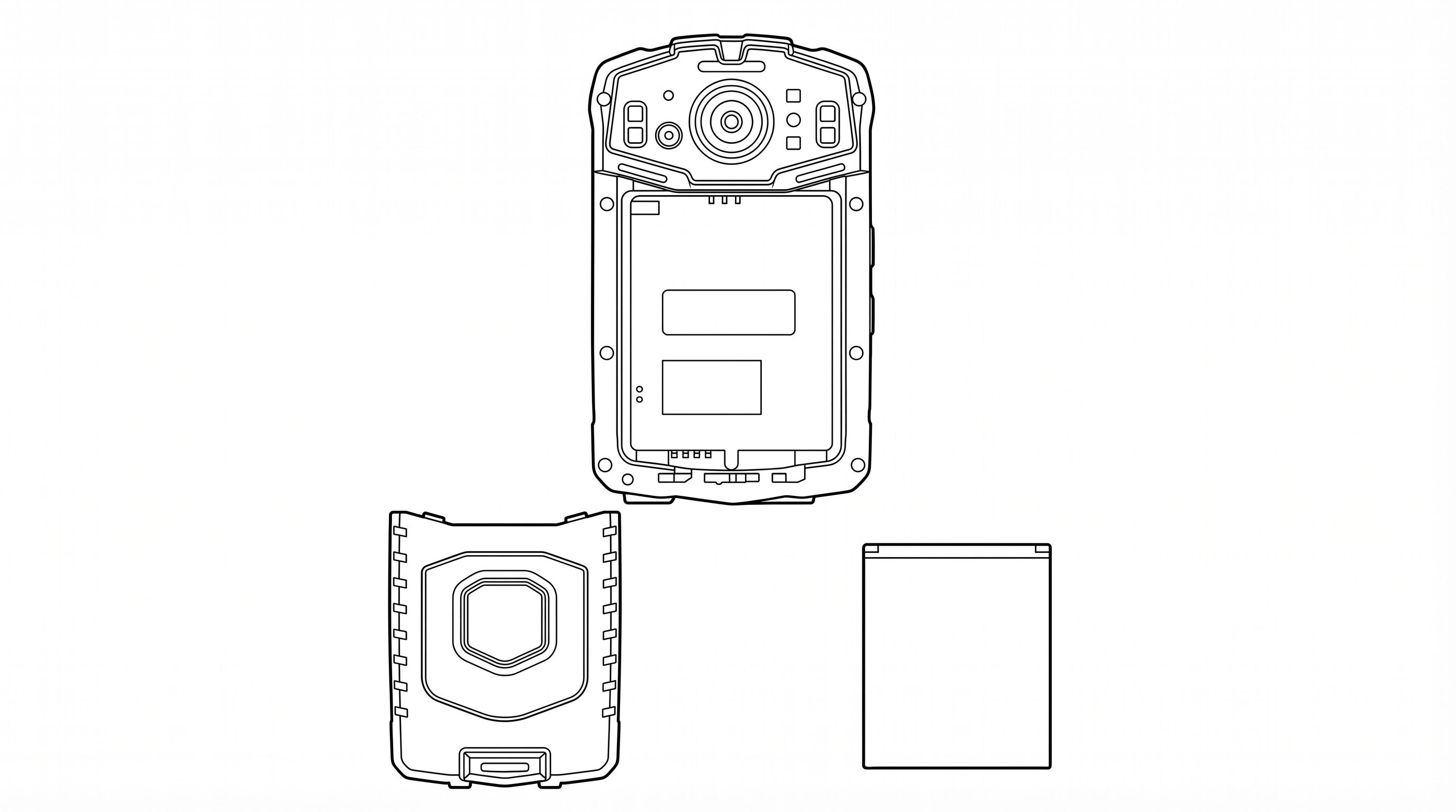
The FCC ID label is located inside the battery compartment, under the battery. To view the label:
The label contains the following information:
Electronic Labeling: FCC identification is also accessible electronically through the device settings menu. Navigate to Settings > About Device to view the FCC ID and regulatory information on-screen.
Manufacturer:
Patrol 6, LLC
2843 E. Robin Lane
Phoenix, AZ 85050 USA
For technical support, warranty claims, or replacement parts, contact Patrol 6: